Tuesday, December 30, 2008

Removing A Civil 3D Object Without Using the AutoCAD Erase Command

Sometimes using AutoCAD commands on Civil 3D objects is okay and sometimes it causes problems. For example: deleting parcel segments or pipe network objects. According to Autodesk, deleting a pipe using the AutoCAD erase command has been corrected in Civil 3D 2009, but since I know some of you may still be using Civil 3D 2008 or earlier, I'm going to show you the proper way to delete an object in Civil 3D.

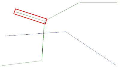
Here I have two pipe networks Water (blue) and Wastewater (green). After a round of revisions, the pipe and one of the structures in the red rectangle needs to be removed.

I know it's very tempting to just run the erase command and select the structure and pipe to be deleted, but that's what causes the issue. Here's the proper way to delete the structure and pipe.

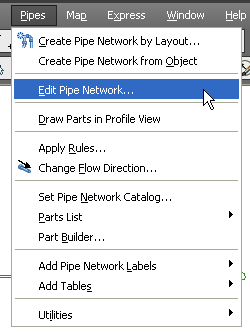
From the Pipes menu list, select "Edit Pipe Network...".

The command line prompts you to "Select part from pipe network:". After you select the pipe or structure you are deleting, the Network Layout Tools toolbar will appear. The tool you want is the "Delete Pipe Network Object".

After selecting the "Delete Pipe Network Object" tool, you are prompted to "Select Structure or Pipe". Left click on any structures or pipes that you want deleted from the network.

The reason you should always delete pipe network objects using this tool is because the pipe network part must be disconnected from other parts in the network before they are removed from the drawing.

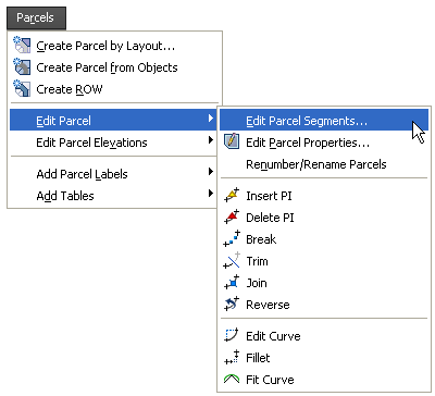
Something similar happens with parcels so be sure to delete parcel segments using the appropriate tool as well.

[Parcels - Edit Parcel - Edit Parcel Segments]
The tool is labeled "Delete Sub-entity".

Thursday, December 11, 2008

To Link or Not to Link

If you've ever worked with assemblies, you've probably experienced a subassembly not looking the way you initially created it. Now, I don't know what causes it, but I did learn a very simple way to fix it this year at Autodesk University.

Here's the original assembly:
Here's the assembly after a few of the subassemblies took on a mind of their own:
Even though the assembly will work as expected, it still bothers me that it doesn't visually look correct. Here's how to fix the visual misrepresentation that you're seeing:
  1. Select the assembly. The assembly is represented by the green line with a blue circle at it's midpoint in the images shown.
  2. Right click and select Assembly Properties... from the list.
  3. In the Assembly Properties, left click on the Construction tab. You must select this tab or the fix won't work.
  4. Now left click on the OK command button.
There you go, all the subassemblies should now be drawn correctly.

Saturday, December 6, 2008

The Future of Civil 3D...

Well Autodesk University 2008 is finally over and I'm sitting here in the airport waiting for the airplane to arrive that takes me back to Austin. My brain is so full of stuff that I want to share with my fellow employees and I can't wait to get back to work and start sharing.

I would like to thank Dana Probert for spending some time with T. J. and me visiting about Civil 3D. Dana is such a great person and is always excited to share her knowledge and ideas with everyone she meets. Here's one of the things she shared with us.

Autodesk is always looking for people like you that want to help influence the future of the software. There are several ways to do this.

  1. One way to influence the future of Autodesk products is to join AUGI at http://www.augi.com and submit requests to the Civil 3D wish list. There is also a discussion forum for the Civil 3D wish list items. Be sure to read the details about submission cycles and check the forums often in case someone has a question about the wish that you submitted or you can ask someone else questions about their wish. Most of the time there are more wishes that I want than the ten for which I cast votes (the limit of votes you get for wish list items). So maybe you can add your agreement to a wish in the discussion forum even if it doesn't make your "top ten" list.
  2. Send an email to ANYONE at Autodesk using the standard Autodesk email format FirstName dot LastName at autodesk dot com. This includes emails to Carl Bass. Now I'm not saying that Carl Bass is the one that's going to read that email, but the email will get forwarded to the proper department if it's appropriate. By an appropriate email, I'm suggesting that you include opinions or suggestions for future releases of the product. Sending an email saying that you hate the product or that it crashes too often will not make the software any better. Saying that you would like to be able to edit parcel line segment lables could help shape the future of the software. (I submitted this wish list item and even though it wasn't in the top ten, this ability became available in Civil 3D 2009.)
  3. Another way that you can get involved with the future of the software is to sign up for beta testing of the product. This can be done by visiting the MyFeedback website at http://myfeedback.autodesk.com and creating a login. You will need to be active in the discussion forums if you want to be selected to test the software. The developers do read these discussions so again, be positive and give suggestions on what you would like to see done with future releases. If you are selected to participate in a beta test of the software, make sure that you give feedback on what you see and how you like it. Also keep in mind that by the time beta testing starts, the current feature set is pretty much locked so don't think that you'll be able to request a new feature at that time and see it in the final deliverable product. The development team definitely reads these forums and responds appropriately. Many of these discussions result in future enhancements of the product. Participating in MyFeedback with Autodesk requires you to digitally sign a Non-Disclosure Agreement so discussions about what you see on the site must remain there. It's very important!
  4. While you are browsing the MyFeedback forums, volunteer to participate in Usability Studies. If you don't see a Usability Study that you want on the MyFeedback site, contact Kate Russell at (yep, you guessed it) Kate dot Russell at autodesk dot com. Kate is a Usability Engineer for Autodesk and if you tell her why you should be selected to participate in future studies, she will add you to the list of potential usability study participants. Be forewarned, if you are chosen, then you'll be required to sign appropriate Non-Disclosure Agreements that bind you and your company to secrecy about . There are several reasons for this and Autodesk if very strict about you abiding by these agreements. DON'T TAKE THEM LIGHTLY!
You can participate in multiple product studies or betas, but don't get involved in so many that you don't give each test the time necessary to truly evaluate it properly.

Well, looks like the plane has arrived, so now that you know how to participate, get out there and get involved so you too can be a "co-designer" of future releases of Civil 3D!

Wednesday, December 3, 2008

AU 2008: Class Day 2

Wednesday at AU 2008.

T. J., Margie and I spent some time visiting with Peter Southwood of Autodesk about making AutoCAD Map do some things that ArcView can do. As for me, I learned a lot during that short time and really wanted to stay and talk with him more, but I had a class to attend. As if the information he gave us wasn't enough, he also gave us a cool parting gift (an Eco-friendly Solar Charger). SWEET! Maybe we asked some really good questions.

The action recorder class with Lee Ambrosius was very good and my lab partner was from nearby Temple, Tx. As we were leaving class, I mentioned that I should be seeing her in Temple in February during the Civil 3D User Group meeting. That's when she asked if I had ever been at the college in Temple. I laughed and said yes, that I presented there in February, 2008. She then explained that the whole time we sat by each other, she felt that she recognized me, but couldn't quite place where or when. Now she knows.

The subscription lunch finally had something that was halfway edible for me (I'm such a picky eater) and the topic wasn't bad either. More info on how subscription customers will be getting more for their money. Since there were still a few open chairs in the room, I sent a text message to T. J. to come join Margie and me at the luncheon. He liked the food much more than I did, but that doesn't surprise me.

The afternoon Detention Pond Design class was really good even though I had to leave early to attend James Wedding's AU Unplugged session. I will definitely be watching the video of this session when it gets posted. I learned so much in the first hour of that class that I now feel that using the H&H software might be worth investing some of my time. So if any of you know John Sayre, tell him I said thanks for presenting a great class in a way that us less experienced folks could learn something. John really took the bite out of some of those H&H acronyms. Also, tell him that I'm sorry for bugging out early, but blame James for that one.

James' AU Unplugged session proved to me that many of the problems we face with project setup and directory structure are not unlike those that other companies face. It seems that there are many ways to skin that cat and there's no right or wrong answer in a lot of cases. Is there room for improvement? Always. Some improvements can be achieved by us as users and CAD Managers, and some will require help from Autodesk. We'll see where the future takes us.

I missed the AUGI annual meeting because I was attending Dana Probert's Point Cloud class. Good class and great handout (even if it was put together in the wrong order). I always learn someting in Dana's classes. Even if it's just applying the things that she teaches in a different way. Dana even gave us an incentive to fill out our class surveys. If we filled everything out before 8pm Wed. night, we could enter a drawing for a chance to win a free AU pass for next year. Well, Dana, I pulled out my handy dandy laptop and tried to do that very thing. I logged onto the website and the survey for your class was not available yet. I did confirm, however, that all my other surveys had been entered. Does this mean I'm still in the running for a pass or not?

I finished off the evening with dinner at the exhibit hall and I even played what I think was Guitar Hero on a wii. Some people will do just about anything for a chance to win a Mastering Civil 3D 2009 book. Okay maybe it was the chance to win a wii and the open bar that got people out there making fools of themselves. Lisa Pohlmeyer was kind enough to video the moment for me (I was trying my best to play bass guitar) so I'll get that posted as soon as I can.

As for Tuesday's post, I'm hoping to have it approved by lunch tomorrow. Until then, I hope all the AU attendees have a great evening and don't snore in class tomorrow morning.

AU 2008: Class Day 1

Tuesday, December 2nd, at Autodesk University 2008.

This day was non-stop. Classes all morning and lots of networking throughout the evening. Tuesday's classes were outstanding and I made sure to stop by the registration center and fill out the survey on every class I attended.

For lunch I attended a subscription luncheon and we were treated to a discussion on the future of subscription services. It appears that the Autodesk subscription folks have been listening to "the people" and are trying to provide what we want. Autodesk will be providing product updates on a schedule more in keeping with other product lines such as Adobe. This means that we might be seeing product updates as often as quarterly depending on when the product is truly ready for the public. The subscription customers will be able to download and install these updates and enhancements before they are added to the following year's products that are released to the general public. This methodology has already been put into affect by offering three product enhancements for AutoCAD 2009 (AUGI wish list items, PDF attachment, and 3D printing). Unfortunately, these same enhancements were not offered for vertical products so I haven't been able to enjoy these new features. I have, however, found some enhancements for Civil 3D including the conditional subassembly. If you haven't been to the Autodesk subscription website lately, you really should give it a look. You might find something you like while you're there.

Between afternoon classes, I managed to schedule a Civil 3D Usability Test where I was able to meet Kate Russell with Autodesk and to see another Autodesk employee, Tarang Taunk, that I met during a Civil 3D Usability Test at AU last year. Kate and I have spoken on the phone several times, but we've never met in person. It's great to finally have a face to go with the voice.

During the session, I was given the opportunity to voice my opinions about certain aspects of the current and possible future software. It really made me feel that I had a voice in the future of the software. When I had completed the session, I was given a sticker to put on my badge. It says, "AutoCAD Civil 3D co-designer AEC Usability". There were also other benefits for participating in this study so if you get a chance, stop by the AEC Usability Center is located at Zeno room 4601 in the AEC Campus on the 4th floor. Even if you don't get to test something at AU this year, maybe you will get a call later in the year.

During the day, I posted a few status messages on my twitter account. During a class on conditional subassemblies being instructed by Nick Zeeban, I posted my location. One of the guys following my tweets, Josh Nelson, happened to be in the same room as me. We were able to meet and chat after the class.

Josh joined me at the AU blogger social where we spoke with Shaan Hurley before speeding off to the top secret preview of the "possible" future of Civil 3D. That room was filled with a who's who of Civil 3D. WOW! During the gathering, I was able to see some of the Autodesk employees that do the webcasts such as Dave and Dan. I also met Rob Todd, who is evidently very pleased with some of things I previously shared with him about the product. I can't wait to visit with Rob more in the future.

After all the oohs and aahs were done, I slipped down the hall to attend the DC CADD social. There I visited with many DC CADD employees including Gabe, Matt, Mark, Mike, and Kim.

Next I was off to the opening of the exhibition hall and dinner. What I didn't realize was that there were four different types of dinners being offered. I happened to get in the "Fajita" line. Not sure if that was considered the "American" or "Latin American" food line. Honestly, I'm not used to such "high end" food so it's hard to find anything that I'll eat at any of these meals.

Tuesday, December 2, 2008

AU 2008: Day 1

So it's Monday, December 2nd (Day One), at Autodesk University 2008. I arrived at the Venetian (the host hotel) around noon. I could immediately tell that many AUers had already arrived (evidenced by the numerous AU badges that could be seen hanging by a string around the neck).

As I continued my way toward the casino area, I recognized a familiar face. It was Scott McEachron. He gave me a hug and we chatted for a bit. Then I headed down the hall to look for AU registration area.

On the way to the registration area, there were several ladies with AU signs. They were very nice and helped point me in the right direction (since registration was not in the same location as last year).

As I was nearing the entrance to the registration area, I passed by Shaan Hurley. He was in an animated conversation with several other people. I wanted to say hello, but it didn't seem like a good time so hopefully I get another chance to speak with him while I'm here at AU.

I continued to registration and that went very smoothly. There was no line at all to access the registration computers, but if you looked closely, you would notice that there was a line for folks that had used the registration computers and were waiting to pick up their packets. I chose a row that only had one person in the packet pickup line and selected a computer to use.

The gentleman in my line was taking FOREVER asking questions after getting his packet. Finally another lady brought my packet to his left so that I didn't have to continue waiting. Everything I needed was in the packet including my badge, ribbons, and subscription t-shirt and information (though I won't be able to wear the t-shirt in public because it's an XL and I wear a Medium).

Autodesk seems to have really taken this recycle thing to heart because the bag to hold my stuff and the spiral notebook were made from recycled materials. Part of the bag is a different color or colors.

At this point, I took a quick peak at the contents of my packet. I was concerned that I did not receive tickets for subscription meals, so I went to visit with the Subscription Center FAQ folks. They politely explained that all I needed was my badge. COOL.

Next I went straight to the Marin mountain bike that was in the room (since I'm a mountain biker myself). It was at a sustainable design exhibit in the registration area. I completed the survey about sustainable design and gave them my contact info in case I win the bike (crossing fingers). Then I reviewed the sustainable design board and added my own idea for how to help improve sustainable design for the future. For this idea, I received my choice of metallic water bottles. COOL.

Then I made the trek through the buttons. I grabbed any that I thought applied or were funny including "Drafty" and "Got Work". There were so many from which to choose. Then I debated about printing my schedule, but I kept reminding myself that I already had a printout in my suitcase.

As I was about to leave the registration area, I noticed another familiar face. It was Lynn Allen. She was interviewing an AU attendee about his experience at AU so far. Though there was already a crowd gathering around her, and since I'm not real fond of cameras in the first place, I headed in the opposite direction.

Next I went to register at the Venetian. In case you've never been to Las Vegas or AU, there is a TON of walking. I made the trek to the hotel lobby and got in line, only to be sent around the corner and upstairs to a different registration area. I was told that many of the AU rooms had already been assigned and that not many others were ready for occupancy. I was given the choice of a handicap accessible room or a room with a "great view of the strip". The caveat was that the "room with a view" was an extra $25/day. No way, Jose. I declined the "room with the view" and went for the handicap accessible room. Though I would prefer the room be saved for those that need it, the accessible room was a great choice for me. In the elevator on the way up to the room, something occurred to me that proved correct. The accessible room was very close to the elevator. YEAH!

I dropped off my AU stuff then went for a walk down the strip looking for a place to eat. I settled on Outback Steakhouse (at the Coca Cola and M&M store, then I returned several hours later to get ready for the AEC BIM Mixer.

I had already spoken with Lisa Pohlmeyer and she was with some of the current and previous DC CADD employees. They were heading to the Mixer within the hour (though I thought that was a bit early).

I brought my stuff from the car to the room, took a shower, and got ready for the Mixer. I headed directly to the Sands Expo area and found the first AU information lady. She directed me to the fifth floor and up the escalators I headed. As I got off the escaltor, I noticed that a line was already forming. I thought that I had arrived too late and would have to wait for someone to leave before I could enter the room. Actually, I was just too early and ended up being near the front of the line when the room finally opened.

During my wait, I visited with several AU attendees that were near me in line. We even ended up at the same table after getting our meal and drinks. One gentleman was a Department of Defense employee and the other worked in the structural industry. We had a nice visit about our experiences with Autodesk products.

Later during the Mixer, I found Lisa P. and the DC CADD (now and then) crew. I visited with Lisa, Gabe, Mark Martinez, Scott Durham, and Matt Castelli. Before she left the mixer, Lisa introduced me to Angel Espinoza. I was thrilled to meet him and we spoke about what portions of Civil 3D 2009 were giving me the most issues (my response was pipes and feature lines for grading = crash, for ease of use the problem area = pipe labels).

I then left with Lisa, Scott, and Matt to go to the Venetian Food Court. T. J. joined us later from the MGM Grand. We all had quite a discussion on the economy, stocks, and iPhones before retiring to our rooms.

Well, that was Day One. I hope the classes I chose are great ones.
Thursday, November 6, 2008

What's Wrong With My Text?

In case you haven't experienced it yet, working with true type fonts in AutoCAD can sometimes be a challenge. Here's one such example:

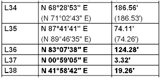
A fellow employee sends me a PDF showing a line table that was created using text objects with Arial and ArialBold font styles (both are True Type Fonts). The line table was created in two parts, then copy/pasted together into one table. Here's a portion of the result:


Notice that the Bold text in the first two lines (L34 and L35) is not as dark or thick as the bold text in the bottom three lines (L36, L37, and L38)? We tried using match properties to get the text to match, but the result is the same. That's unacceptable, right?

So here's the secret: The text on the bottom three lines (L36, L37, and L38) is at an elevation of -1.375 and the text on the top two lines (L34 and L35) is at an elevation of 0.

So the next time you are having issues with true type text, check the elevation of the text and maybe this will solve your problem.

Monday, October 6, 2008

Image Plotting Issues

Today we had a repeat issue of plotting a sheet from paperspace that contained tiff images of a two page subdivision plat in model space. The preview looked correct, and everything on the sheet plotted except the two images of the plat. The Plot and Publish Details showed that the plot had been canceled though it wasn't the user that canceled it.

  • We plotted the layout to a different plotter with the same results.
  • We plotted the layout to a DWF and the images appear as expected.
  • We plotted the layout from a different computer and it plotted fine.

At this point, we decided it had to be computer specific. We contacted DC|CADD and Mark Martinez recommended that we uninstall and reinstall driver, plotter, etc. before proceeding any further. We got the same results (everything but the image was plotting) after the reinstall.

So, now we're thinking maybe it's a memory issue. We checked the system settings and the /3GB switch was not enabled on the problem computer. We changed the System Startup settings so that the /3GB switch would be enabled upon boot, then we rebooted the system.

After the reboot, the resulting plot contains everything on the sheet including the two images.

After the plot worked, we checked the size of the tiff images. (Yes, I know, why didn't we do that at the beginning.) Both images were under 300 KB. Hmmm, sounds small enough to me, but hey, I'm not going to look this gift horse in the mouth.

So, SCORE ONE FOR THE /3GB SWITCH!

Viewport Change Scale Lockup

Here's a quick workaround for an issue that has occured in a couple of Civil 3D 2008 drawings. The workaround was found by Matt Castelli of DC|CADD. Here's the deal:

We have a 2008 drawing that contains 8 or so xref overlays. Some of these xrefs have attached xrefs and most have at least one xref overlay. After creating a viewport in paperspace, the viewport scale was changed to 1" = 10'. It worked fine. Then the annotation scale dropdown was selected so that it could also be changed to 1" = 10'. That's when Civil 3D 2008 froze. The only solution was to kill the AutoCAD process tree.

The workaround is:
  1. Unload all xrefs.
  2. Change the annotation scale.
  3. Reload all required xrefs.

The long-term solution is to open all xref drawings and audit, purge reg apps, reset scale list, and detach missing xrefs. Most of this process can be achieved relatively quickly through two utilities released by Autodesk this year.
  1. Scale List Cleanup Utility
  2. Regapp ID Cleanup Utility
NOTE ADDED 10/06/2008: This drawing freezes in 2009 also

Wednesday, October 1, 2008

Walk This Way, Talk This Way

I know, I know. I haven't posted in a while, but this particular subject is well overdue.

I'm sure you all know what it's like to get drawings that have objects in the wrong layer. So today I wanted to share with you an AutoCAD tool that might help you identify layering issues before you ever send the drawing to the client or start working with the drawing in your project.

The tool is called LayerWalk. The tool can be found in the AutoCAD LayersII toolbar. Or it can be accessed from the command line by typing laywalk and pressing enter.


After executing the command, a dialog box will appear that shows all the layers in the current drawing including xref layers.


By left clicking on any layer in the list, you can see what objects are on that layer. For us civil folks, it works great for checking the layers in a survey drawing before you start working with the file.


Unfortunately, it can work with Civil 3D objects if you set up your styles correctly. For example,create an alignment style with the alignment lines, arcs, and spirals on layer ALIGN. Now create an alignment object on layer WW-A-ALIGN. During execution of the layerwalk command, select only layer ALIGN, and you will see all the alignment linework in the drawing. If you select only layer WW-A-ALIGN, you don't see any alignment linework in the drawing.

On the other hand, create your alignment style with the alignment lines, arcs and spirals on layer 0. Now create an alignment object on layer WW-A-Align. During execution of the layerwalk command, select only layer ALIGN, then you don't see any linework. If you select only layer WW-A-ALIGN, then you see only the WW-A alignment linework.

Now don't forget to audit then purge your drawings (including regapps) and it just might brighten someone's day.

Monday, June 23, 2008

Sheet Set Publishing Part 1

Since I began working with Sheet Sets, I've used the "Insert Sheet List Table" on my cover page. However, I ran into one issue almost immediately. How do you add a sheet that is being plotted by another firm (such as the landscape and electrical plans)? Here's how I resolved the issue:

  1. Create a blank drawing in your plans directory and name it "Sheets_By_Others.dwg" or something that seems appropriate for the sheets. Since there will be nothing in the drawing and layouts, it's not necessary to create a separate drawing for each sheet.

  2. Create a separate layout for each sheet that will be plotted such as L-1, E-2, etc.

  3. Add these layouts to your sheet set. Include the sheet name and descriptions as shown on the sheets you received from the other firm such as "Landscape Details and Calculations" just as you want it to appear on your sheet list table.

  4. In the Sheet Set Manager, right click on the sheet name (L-1 for example) and choose "Properties...".

  5. The fourth option from the top is "Include for publish". Change this property from Yes to No. This will keep the blank layout from plotting when you publish your set by right clicking on the sheet set name and selecting one of the "Publish" options.

Friday, May 23, 2008

Vista Out, XP In

For those of you that have "had it" with Windows Vista. PC Magazine has posted instructions that will take you step by step through the process of downgrading from Vista to XP.

How to Downgrade from Vista to XP

As for me? I'll stick with Vista for now.

Thursday, May 1, 2008

From Deed to Polyline with Civil 3D

Drawing a line or polyline based on bearing and distance in AutoCAD based products can be accomplished in several different ways. Today I'm going to discuss the method that I use in Civil 3D.

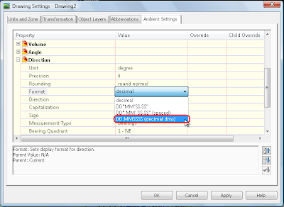
The first thing you need to do is to change a setting to make entry of bearings as degrees minutes seconds much easier. If the Civil 3D toolspace is not already visible, type showts and press enter at the command line. Select the Settings tab, then right click on the drawing name and select "Edit Drawing Settings...". Select the Ambient Settings tab.

In the Property column, scroll down to the section labeled Direction. Verify that the Unit Property is set to degree, then lft click on the value column next to the property labeled Format. It may be currently set to "decimal" or something similar. Left click on the value a second time and a drop down list will appear. Select DD.MMSSSS (decimal dms) from the list, then Apply and OK.

Start the polyline command and pick your start point. At the command line, type 'bd to enter the bearing-distance transparent command. The command line will prompt you to select a Quadrant.

Quadrants - NE = 1, SE = 2, SW = 3, NW = 4

Press 1 for Northeast then press enter. The next prompt is requesting the bearing. Just above the >>Specify bearing: prompt in the command line, you can see that the current direction unit is set to degree, Input : DD.MMSSSS (decimal dms) because of the change we made in the ambient settings. To input the bearing 15d17'32" in the DD.MMSSSS (decimal dms) format, just type 15.1732 and press enter. [WOW, isn't that way easier?] The final prompt is to >>Specify distance: (500.00 for this example) then press enter.

Civil 3D will now calculate the coordinates for this bearing and distance and feed it to the command line. This in turn will draw the line or segment of the polyline before returning to the prompt for the next quadrant.

So what happens when you mistakenly type in the wrong quadrant, bearing, or distance? If you're creating a polyline, then you can just use undo that's built into the polyline command. Here's how it works:

After completing the prompts with the wrong information, press the escape key one time. This will get you out of the transparent command and back to the normal polyline command line prompt. At that point, you can type U and press return. This will remove the last segment of the polyline that was just created. Then just type 'bd and press return to enter additional bearings and distances. You can also escape back to the polyline command to change between arc segments and line segments.

Sunday, April 27, 2008

How Many Inches in a Meter?

I know that the easiest way to convert your existing template to a new version of Civil 3D is to just open and save the template. However, you will be missing some of the new settings that just got implemented into the new version of the software.

One of these new settings can be found in the Drawing Settings dialog box, Units and Zone tab. There is a new "Imperial to Metric conversion" setting there. It defaults to "International Foot(1 Foot = 0.3048 Meters)" for the OOTB templates. This means that when you open and save your existing template, it will also be set to "International Foot".

So depending on your location and project, you might need to change this setting to "US Survey Foot(39.37 Inches per Meter)".


Although it could be found in previous versions, you may not know that there is a similar setting in the Land XML export settings under the Data Settings properties.

Friday, April 25, 2008

*Warning* Multiply owned object

Since I'm already having to use this in Civil 3D 2009, I'm going to post it here so it's easier for me and others to find in the future.

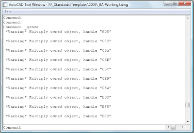
Isn't it frustrating when you get this type of warning message?


Great. Now what do I do? Is the drawing corrupt? Do I have to start from scratch?

Some discussion forum posts suggest that wblocking the drawing can help. Yes, it does get rid of the warning messages, but you could lose all your styles, object layer settings, defaults, etc. That's not acceptable.

Well, according to Scott's Superman post, there is a command you can type to get rid of the problem object (Replace C5C with the handle shown in your command line):

(entdel (handent "C5C"))

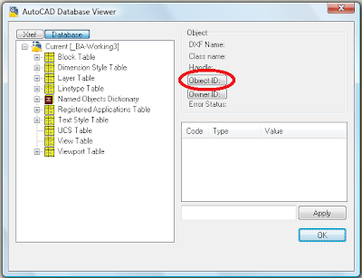
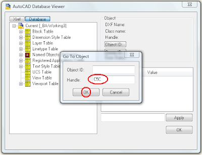
Since it is possible to lose a style or two by running this command, I'd like to know what I'm deleting. So after a bit more research, I found a link to Shaan Hurley's post about DbView for AutoCAD 2007. I followed the instructions and ran the program. It works with Civil 3D 2009. I only wish someone could a "delete" command button for the selected object.

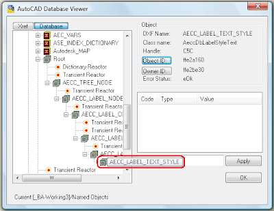
Here's a few screen captures of the DbView program in action:


At this point, I would love to give you some great and wonderful insight as to what you're seeing in that last image. Unfortunately, for now all I can do is look at it and see what type of object will be deleted.

As far as deleting the object goes there are several options for running the command from Scott's post.

  1. You could edit the handle number in a text document, then paste it into the command line.
  2. You could also create a script file on your desktop. Then you would just edit the handle in the script file, save and close, then drag and drop the script file into AutoCAD. You'll need to either put a space after the final )) or make sure and add a return after the final )) in the script file or you'll have to hit enter after running the script file.
  3. Running this command through a lisp routine is another option.
It seems to me that every time I've seen this warning message, it's always been when I have been dragging styles between drawings. In Civil 3D, it definitely happens when you drag child styles into a drawing that already contains the parent style. This happens even if the parent styles were just created by dragging them from the same drawing. Hopefully it can be fixed with C3D 2009 SP1.

Thursday, April 10, 2008

Google Map Street View

Go to the google maps website: http://maps.google.com

Click on Street View to see the locations where street views are available.


Type in a street address including city and state. If a street view is available, there will be a small image of the street view at that address.

Click on the image and you will see an enlarged image of the street view at this address.

There are several arrows denoting directions you can move up or down the street.

You can also rotate right, left, zoom in, and zoom out using the icons

Try this one as an example.

549 S Lamar Blvd Austin TX

Left click on the image shown, then select the rotate right icon.

You will now see the street view of the Central location of Bicycle Sport Shop in Austin, Tx.

In this example, you can also select from N (north) on S Lamar Blvd or S (south) on S Lamar Blvd.

Special thanks to Mark R. for showing me this one.

PVLS PART 4: Offsetting a Profile View Label

This is Part 4 of a series on Profile View Label Styles (PVLS). This post may not make a whole lot of sense if you haven't seen the previous posts in this series. Please take a moment to read them before continuing to read this one. Here's a link to each:

PVLS PART 1: Creating Profiles for Labeling Crossing or Connecting Pipe Flowline Elevations

PVLS PART 2: Creating the Style for the Connecting Pipe Flowline Elevation Label

PVLS PART 3: Labeling the Crossing or Connecting Pipe Flowline Elevations

To use the Offset Style created in this series, you'll need to create the label style first. (Instructions for creating an offset label style can be found Part 2 of this series.

After the style has been created, right click on the style and select New... in the Settings tab of the Toolspace. For Profile Views, this will create a "Child" of the original style. It will have all the same properties and components of the original style at the time that it is created except those that you change.

On the Information tab, rename the text inside the brackets [child] to [RT-0.3]. That means that we will be creating a style that moves the text right 0.3 inches. Go ahead and left click on Apply then select the Layout tab.

Remember how we deleted the original text so that the first component was "Line for Text". This is where it comes into play.

Go to the Line section and change the Start Point X Offset to 0.3, then Apply and OK. Now place the style in the drawing or change one of the existing labels to use this style instead. Here's a screen capture of the original parent style and the new offset RT child style.


There are other ways to change the style as well. Try changing these values and see how they affect the style:
  • The length of the "Line at Insertion Point"
  • The length of the "Line for Text"
  • The Start Point Y Offset of the "Line for Text"
You should never change the values of the "Offset Connection Line", because they will always follow the start/end of the other lines in the style.

Well, that's it for my series on Profile View Label Styles. I hope you found it useful. Feel free to post a comment if you have questions or if you just want to request a topic for a future post.

Technorati Tags:

PVLS PART 3: Labeling the Crossing or Connecting Pipe Flowline Elevations

This is Part 3 of a series on Profile View Label Styles (PVLS). You should also read Part 1 and Part 2 of this series for additional information.

To label a crossing and/or connecting pipe flowline elevation, you'll need the style created in Part 2 of this series and profiles for both the main line and the crossing/connecting pipes as described in Part 1 of this series.

After you have the style and profiles created in your drawing, the rest is really simple.
  1. Zoom into the connecting pipe that you want to label.
  2. From the Civil 3d Profile menu, select "Add Profile View Labels", then "Add Profile View Labels...".
  3. In the Add Labels dialog box, select the style that you created from Part 2 of this series (mine was called Connecting Pipe Label).
  4. Choose a Marker style if you want one. I don't generally use one for this style.
  5. Left click on the Add command button.
  6. You will be prompted to select a profile view. Select the profile view by left clicking on one of the grid lines, not the actual profile.
  7. When asked to specify a station, select the endpoint at the flowline of the crossing pipe shown in the profile view.
  8. When asked to specify an elevation, you can either select the same point or specify an elevation for the insertion point of the label.
  9. Repeat this process for other connecting pipe labels that are visible in this profile view.
  10. If you need to add labels in other profile views, you'll need to left click on the Add command button again to select a different profile view.
So now the label is placed, but there aren't any elevations shown. Here's the secret:
  1. Select all the connecting pipe labels in one profile view and then look at the properties listed on the labels. There is a Civil 3D section that contains a listing for Profile1 Object and Profile2 Object. They will be set to by default.
  2. Left click on the for Profile1 Object and set that to the profile you created for the flowline of the main pipe.
  3. Left click on the for Profile2 Object and set that to the profile you created for the crossing and/or connecting pipes and pipe size changes.
Now you have the flowline elevations and all you have to do is editlabeltext on the style to change the name of the utility line and modify the pipe sizes. As I said in my first post, I'm sure you can take this style further to get the pipe sizes in it. Also, you would need to make a copy of the style and modify the text for grade breaks, and crossing pipes.

Well, that's it for Part 3. In Part 4, I will describe how to use the offset capability that we put in place when we created the Profile View Station Elevation Label Style in Part 2 of this series.

Technorati Tags:

PVLS PART 2: Creating the Style for the Connecting Pipe Flowline Elevation Label

This is Part 2 of a series on Profile View Label Styles (PVLS). You can view Part 1 of the series here.

Here's the step by step guide to creating the Station Elevation Profile View Label Style. The way this style is created will enable you to easily establish offsets in child styles as needed. That will be explained in a Part 4 of this series.
  1. If toolspace is not visible, type showts at the command line and press enter.
  2. Select the Settings tab.
  3. Double click "Profile View" in the list under your current drawing name.
  4. Double click "Label Styles".
  5. Right click "Station Elevation" and select "New...".
  6. On the Information tab, type a name for your style. I'll use Connecting Pipe Label for this example.
  7. On the General tab, set the layer as required. I'll use PROF-VIEW-TX for this example.
  8. On the Layout tab, delete the default "Station & ELevation" component (yes, the "L" is really capitalized) that is created by clicking on the near the top middle of the Label Style Composer dialog box. I do this because I want a different component to be the first one that appears when the Layout tab is selected in the future.
  9. Select Line from the Create Component dropdown list.
  10. Under the General section:
    1. Change the Name property to Line for Text,
    2. Set the Start point anchor point to Middle Center.
  11. Under the Line section:
    1. Change the Length to 2.0000",
    2. Set the Angle to 270° 00' 00",
    3. Set the Start Point Y Offset to -0.5000". This moves the beginning of the line down 0.5 inches from the point you select for placing the label.
  12. At this point, you're probably looking at the preview side of the Label Style Composer dialog box to see how things are looking. Unfortunately, the default preview state for a Profile View Station Elevation Label is set to Depth Label Style. So click the drop down arrow near the upper right corner of the Label Style Composer dialog box and select "Station Elevation Label Style" to watch the style update as you apply the changes.
  13. At this point, go ahead and select Apply so that everything up to this point will be saved.
  14. Create another line component (same as step 9).
  15. Under the General section:
    1. Change the Name property to Line at Insertion Point,
    2. Set the Start point anchor point to Middle Center.
  16. Under the Line section:
    1. Change the Length to 0.2500",
    2. Set the Angle to 270° 00' 00".
  17. Now create one more line component (same as step 9). This may seem unusual, but it will make sense at the end of the post.
  18. Under the General section:
    1. Change the Name property to Offset Connection Line,
    2. Set the Start point anchor component to Line at Insertion Point,
    3. Set the Start point anchor point to End,
    4. Set the Use End Point Anchor to True,
    5. Set the End Point Anchor Component to Line for Text,
    6. Verify that the End Point Anchor Point is set to Start.
  19. Select Apply again to save the changes up to this point. The preview tab will show that the label currently appears as if there is just one solid line.
  20. Create a text component from the create component list.
  21. Under the General section:
    1. Change the Name property to Station and Flowline Text,
    2. Set the Start point anchor point to Line for Text,
    3. Set the Anchor Point to End.
  22. Under the Text section:
    1. Edit the Contents as follows:
      1. On the format tab, set the Justification to Left,
      2. Insert text appropriate for the style you are creating. For my example, I used this text:
        STA <[Station Value(Uft|FS|P2|RN|AP|Sn|TP|B2|EN|W0|OF)]> SSL-XX=
        STA 1+00 SSL-XX
        FL (XX")=<[Profile1 Elevation(Uft|P2|RN|AP|Sn|OF)]>
        FL (XX")=<[Profile2 Elevation(Uft|P2|RN|AP|Sn|OF)]>
        I also force the XX values to a different color so that I know that these values have to be manually edited and updated as required. It ends up looking something like this:
    2. Set the Attachment point to Bottom Right (Don't ask me why. I think it should be set to Top Left, but once the text is perpendicular to the view, it seems that you have to set it to the opposite of what you think it should be.)
  23. Apply, OK, and your style is complete.
Well, that's it for Part 2. In Part 3, I will describe how to place the Profile View Station Elevation Label Style that you just created.

Technorati Tags:

PVLS PART 1: Creating Profiles for Labeling Crossing or Connecting Pipe Flowline Elevations

This is Part 1 of a series on Profile View Label Styles (PVLS). I will discuss how to label the flowlines of connecting pipes in a profile view. Armed with this information, you should be able to create your own style that shows flowlines of pipes at crossings and at changes in pipe sizes.

Well this is one label style with which I've been wrestling for some time. Then while creating an offset label style the other day, it just hit me how easy it would be to get the two flowline elevations into one style. Now, at this point, the pipe size in this particular style has to be edited manually, but maybe this style might give you some ideas on how to get everything you want labeled automatically.

The first thing you need to do is create a profile style with Line, Circular Curve, Symmetrical Parabola, and Asymmetrical Parabola component types visible, but on a "no-plot" layer. For my style, I've create a layer called _no-plot-profile and set the Plot property to "No".


Now create a profile by layout that follows the flowline of the main pipe in your profile view. Be sure to use the "no-plot-profile" style that you just created. This profile can also be used to label your pipe flowline elevations (such as the elevations shown in a band style).


Now create a second profile by layout that connects the flowline of all your crossing or connecting pipes. You can also tag the end of the smaller pipe at a pipe change (since a profile can't be exactly vertical). The second profile should look something like this:


Here's a zoomed in view of the three major locations where I use the "crossing pipe" profile. (Just click on the image to see an enlarged view.)


Well, that's it for Part 1. In Part 2, I will describe how to create the Profile View Station Elevation Label Style.

Technorati Tags:

Saturday, March 22, 2008

AutoCAD 2009 Properties Improvement

We've all gotten used to the fact that if you select multiple objects, then view the listing in the properties box, you'll see "All (#)" in the listing. This is also the case for viewports made from an object. If you select the viewport, you'll get "All (2)" in the properties drop down list. You have to select viewport from the drop down list to access only the viewport properties.

Well in AutoCAD 2009, in addition to all the other improvements, there's one little jewel that you may not notice immediately. If you select a viewport created from an object, you will still be selecting two items (one viewport and one polyline), but the default view in the properties box will be "viewport (1)". If you select the drop down list, you can still access the polyline properties for the viewport.

Way to go Autodesk!

Technorati Tags:

Wednesday, March 12, 2008

Don't Plot Those Image Frames Ever Again

Have you ever sent your plot to the plotter only to notice that the frames are visible around the images?

The problem is that if you set the frame visibility off (imageframe=0), then you can't select the image and execute commands on it such as draworder.

So you can spend your time changing the visibility of the image frame on then off, or you can take the advice of Lynn Allen and set the imageframe variable to 2. This will allow the frame to be visible, but it won't plot. This funcationality has even been added to AutoCAD LT 2009.

One more thing before I go. This variable is drawing specific, so you can set it in your template and never have to worry about it again for new drawings created from the template.

Technorati Tags:

Thursday, March 6, 2008

Become an AutoCAD Power User #2

Set IMAGEFRAME to 2 to display the image frame, but not plot the image frame.

Hold F3 to temporarily reverse the object snaps setting.

Run xlist to list the properties of an object in an xref.

Set maxsort to a higher number if new layers are no longer being sorted alphabetically. The default value is 200. The maximum value is 32767.

Technorati Tags:

Monday, March 3, 2008

From Rectangular to Polygonal? No Problem!

Maybe it's just me, but is seems that when your working on drawings that contain multiple layouts, using polygonal viewports increases the regen time on the drawing. Okay, so there's a lot of things that increase regen time, especially if you're using Civil 3D, but I'm only addressing one in particular. (For a more detailed list with recommendations, read Dana's post on civil 3d.com)

Up until last week, I would always create my viewports as rectangular then add a mask or wipeout, if necessary, to place my north arrow and barscale. This method works for objects in paperspace, but if I needed to overlay another viewport, that wasn't the answer. In that case, I had to recreate the viewport, move the new one so that it overlayed the original one exactly (move endpoint to endpoint), then modify the viewport to match the border of the sheet as required.

Well, last week I was shown a new command that really made the process much easier and I've decided to share it with you. The command is vpclip. With this command, you can "convert" a rectangular viewport to a polygonal viewport in seconds. Here's how it works:

  1. While in the layout tab to be modified, begin by entering vpclip at the command prompt and pressing enter.
  2. The command prompt will request that you "Select viewport to clip:". Left click on the viewport that you want modified. NOTE: you must have the layer containing the viewport ON and THAWED to select the viewport.
  3. Next you'll be prompted to "Select clipping object or [Polygonal] :"
  4. If you have already created an object for the new viewport boundary, just left click the object to select it. The viewport boundary will update immediately.
  5. If you want to create the boundary "on-the-fly", just press enter to select Polygonal, then left click each PI of the new boundary. If you forget to "Close" at the end, don't worry, the software will do it for you.

Don't forget that you can use a circle for the viewport boundary as well. Just create the circle in paperspace, then select it as your new "clipping object" when prompted.

Now you can create all your viewports as rectangles, then convert them only when necessary. Hopefully this will help keep your regen time a bit shorter in the future.

Technorati Tags: ,

Thursday, February 28, 2008

What? You Don't Use Bands?

That was the reaction I received during a presentation at my local user group meeting last week.  That group may not remember anything else I said, but that comment definitely got a reaction from the crowd.   So here's the story behind that statement...

Some engineers and companies are very particular about how certain items are labeled on their profile views.  I was working with one of those engineers on a project last year when I ran into a snag.  I was supposed to show the elevations of the profile in the "band" at the bottom of the profile view but I had to add the text "TC=" in front of the elevation.   The problem was that the "TC=" text appeared even on stations that had no profile. 

 Band_Style

Obviously, that wasn't going to work, so I had to find a different way to display this label.  Having recently made some changes to the default profile styles in the company template, I decided to give something a try.  I created a profile label style that looked just like the band style, but it only appears where the profile exists.  That means if the profile only exists from station 1+00 to 12+50, then you'll only get labels from station 1+00 to 12+50 according to the major and minor station labels requested. 

Band_Style2

So here's how you create and use this style:

  1. Open or create a drawing in Civil 3D.
  2. Make sure the toolspace is visible (command:  showts)
  3. Select the Settings tab of the Toolspace.
  4. Double click "Profile" from the list of objects.
  5. Double click "Label Styles".
  6. Double click "Station".
  7. Double click "Major Station"
  8. Now you should see a list of the existing Profile Major Station Labels in this drawing.  The list may only contain "Standard".
  9. Right click on "Major Station" and choose "New..."
  10. Select the Information tab and change the Name of the Label Style to "XX-FG-LT". Replace the XX with the initials of your company.
  11. Apply.
  12. Select the General Tab.
    • Change the Layer to the one of your choice.
    • Set the Orientation Reference to either View or World Coordinate System.  Band_Style3 
  13. Select the Layout tab.
    • Left click the Band_Style4 enough times to remove all existing components from the list.
    • Left click the Band_Style5 to insert a new "default" text object.
    • Change the Name value from "Text.1" to "Profile Elevation".
    • Set the Anchor Point to "Anchor Station Extension"
    • Modify the Contents Value:
      • Left click on the "Label Text" box then left click on the Band_Style6 to change the text value for this label
      • Select all the text in the Text box on the right of the Text component Editor - Contents dialog box and replace it with the desired "prefix text" in the same location (TC=)
      • Make sure your cursor is after the last character of the "prefix text"
      • From the Properties drop down list, select Profile Elevation
      • Set the Precision, Rounding, Decimal character, Sign and Output as desired for your project
      • Left click the CreateMacro to create the macro
      • The result should look something like this:  Band_Style6
      • OK
    • Set the Text Height to the desired value
    • Change the Rotation Angle to 90
    • Change the Attachment to Top Left
    • Change another other border and dragged state settings as required.
  14. Apply
  15. OK

Now all that's left to do is add your new style to a Label Set.  The tricky part is that you have to set the Dim anchor opt to "Profile View Bottom" and adjust your Dim anchor val to an appropriate setting.

Band_Style7

So, that's all it takes to create a band style that only places labels where the profile exists.

Technorati Tags: , , ,

AutoCAD & Vertical Application Bugtracker

If you haven't already done so, please take a moment to visit the AutoCAD & Vertical Application Bugtracker website. It's managed by a great guy named Ralph Sanchez. He's keeping a list of "known bugs" for AutoCAD products that have been submitted to Autodesk.

The website currently lists bugs for the following products:

AutoCAD
AutoCAD Civil 3D
AutoCAD Land Desktop
AutoCAD Map 3D

If you know of any bugs in current AutoCAD or Vertical Applications that have already been submitted to Autodesk, just submit a bug report to the teXupport.net website for all others to see. If you know of a current "work-around" or solution for the problem, be sure to include that information with your bug report. I won't promise any miracles, but Ralph and his trusty band of hooligans may even be able to help you find a "work-around" or solution to the problem.

Ralph will review the submitted bugs to determine that he can duplicate the problem, but Ralph and this website are NOT to be used as your main source of tech support for problems with AutoCAD products. You should always communicate potential bugs directly to Autodesk. Or you can discuss them with your Autodesk reseller, mine is D|C|CADD, if you are current on your Autodesk subscription plan.

While you're browsing the site, review the Downloads Section of the website. This section contains some useful utilities such as "Lock All Viewports" and "Multiple Offset".

The website has an RSS feed so be sure and add this to your favorite RSS reader, such as SharpReader or NewsGator, so that you get updated with the latest reported bug info as it is added to the list.

Enjoy!

Technorati Tags: ,

Friday, February 15, 2008

Vista, You're Fast Again!

As a follow up to my Vista, Why Are You So Slow? post, I finally just changed my "Windows Color and Appearance" to Vista Basic. That helped on the speed issue a lot, but then my screen captures didn't match all the prior screen captures that I had in the handout I was preparing. So I just switched it back to the default settings for "Windows Color and Appearance". Even though I don't know why, the system is "fast" again. I guess the change worked like a reboot or something.

So if you ever have slowness issues with Vista, try switching to Vista Basic in the "Open classic appearance properties for more color options" section of the "Windows Color and Appearance" panel in Vista, then change back to the Aero color of your choice.


Technorati Tags: ,

Who Has Time for All Those Civil 3D Webcasts?

No matter how many times I have visited the Civil 3D Live Webcast page, I have never noticed that the sidebar on the left included a link to a section called Demonstration. Well, I actually followed that link today, and they are several real quick demos of each subject listed.

I viewed the "Section" demo and it wasn't bad. The best part is that it only last a few minutes. Sure, these demos are not going to answer as many questions as watching the full webcast will, but it may be enough to get you started.

In case you do have time for training, there are many sites that include webcasts, screencasts, etc. Here's a short list of sites you really should visit for webcast style training:

Civil 3D Webcasts Page
Autodesk University
Autodesk Subscription Center

The subscription center has eLearning lessons for current and previous versions of Civil 3d. Don't be afraid to watch the older ones. I actually learned some things from the old version lessons that I had never noticed in the current versions. Some of the dialog boxes look a bit different in the older versions as well, but you should be able to follow the workflow of the lesson.

The thing I liked about eLearning on the subscription site is that the lesson remembers where you last stopped. That way you can continue the lesson instead of trying to "fast forward" to the correct location like you have to do with a webcast. You also get to "click buttons" on Civil 3D in some lessons. Of course, you can't click anything other than what you're supposed to click, but it is still sort of a "hands-on" experience.

The AUGI Training Program is also available but I haven't used it yet.

Check with your reseller for webcasts as well. A lot of times they offer free webcasts throughout the year and will sometimes record and post them on their website. For example:

The D|C|CADD Company
Avatech Solutions

Let's also not forget our dependable friends at civil3d.com and the Civil Engineering Community, not to mention the numerous bloggers that can be found on the internet.


Technorati Tags

Wednesday, February 13, 2008

New AutoDesk Product?

With all the hype on AutoCAD 2009, I thought I would take this opportunity to post about an AutoDesk product that I recently purchased...


Even though the Autodesk we know and love doesn't capitalize their D, I still thought it was an "Autodesk" product when I saw it because of the font style and color scheme (white text on dark background).

Sunday, February 10, 2008

Vista, Why Are You So Slow?

I've been using 32-bit Vista Home Premium for several months now. The speed has been good for the most part but for the last week or two, I had noticed everything running quite sluggish. I didn't know what I had done different. The sluggishness even appeared while I was typing things like emails or web posts. What the heck happened to this laptop?

I began searching for culprits by going through the icons shown on the taskbar. I had installed a trial version of SnagIt several days earlier and it started automatically when booted the machine. I exited SnagIt but that didn't seem to help. The sluggishness was still there.

My laptop is an HP and as a result, it has several HP apps running as well. I had already removed or disabled several other HP apps, but HP Advisor was still running. I closed the HP Advisor, but still noticed no improvement.

Then I saw this icon that belonged to OneNote. What was it doing there? Supposedly it was ready and waiting for me to begin creating notes like for the minutes of a meeting or notes from a class I was attending. I didn't ask it to be there, so I'll just exit that program as well. Unfortunately, no exit option was available. I could hide the icon (like that was going to do a whole lot of good). I had to find where this program originated.

So I went to check what services were being started automatically. It wasn't there either. So where the heck was it? I found that it was a shortcut was called "OneNote 2007 Screen Clipper and Launcher" and it was in this folder:
C:\Users\Internet\AppData\Roaming\Microsoft\Windows\Start Menu\Programs\Startup

I removed it and rebooted. Although that did improve the speed a bit, the laptop is still not as fast as it was previously.

I continued to search for additional culprits and felt that the indexing service of Vista was probably involved. I found several websites that discussed different Windows Vista tweaks. Here is one that discussed tweaking the indexing options of Vista.

http://www.vistaultimate.com/tweak-windows-vista-indexing.htm

I made this tweak and even while typing this post (I haven't restarted the laptop yet) I've already noticed a difference. There is no longer a lag between when I type something and when the characters actually appear on the screen.

So is there a bad side to not indexing? I don't know yet, but I do know that the index list hardly ever was indexing the folder or file types for which I ran searches. Now at least there is a shorter file list to browse before I can tell it to "search in non-indexed directories".

Now the indexing wasn't changed within the last two weeks, so there was still an issue. Then I remembered. One of the first things I did when I got this laptop was to uninstall Microsoft Works and install Open Office. I was really going to give Open Office a try and see if I could live without Microsoft Office. I already knew I wouldn't use Works because too many Excel commands that I use often are either different or missing. Well, I gave it a try and although the other portions of Open Office would have been sufficient, I had trouble with Excel again. I guess the "power user" in me appeared and just found problem after problem with using the Open Office replacement for Excel. For most people it worked fine, but some things I just couldn't accept.

So I finally conceded and purchased a legal copy of Microsoft Office Home and Student 2007, but I didn't install it quite yet. I figured, what the heck, I'll go ahead and use the trial version of Office on my laptop before I open the newly purchased product. If I didn't like it or if I had similar problems as I did with Microsoft Works, I would just return it unopened. Now that I look back, I see this as the time when the laptop began its descent into the land of the slugs.

In summary, can I live without Microsoft's version of Excel? Yes.
Will I use other spreadsheets in place of Microsoft's version of Excel? No.

I guess I'll just have to live with that performance hit to continue using Excel the way I want.

Maybe Vista SP1 will take care of this. Well, just in case, I'm not going to expect too much.